Updated 9/2018 with comments on how this has worked out in the last 8 years since I wrote this article.
Re-doing the power systems on Valkyr
When we got the boat it had two optima batteries one in the starter bank and one in the house bank. There were two other group 31 Sea Volt AGM batteries sitting on the boat not hooked up. My plan is to use the two group 31 Sea Volt AGM’s along with 2 identical Group 31’s that I have on my old boat to make a house bank of 440 AH. The two optima AGM batteries will go in the second engine starting bank. These are controlled from the stock DC switch panel that has a 1/2/All/Off switch integrated into it.
To charge the batteries Valkyr had a 3 stage computer controlled portable automotive 1/10/25 amp charger just clipped to one of the batteries. Though it is a very nice charger we would rather that the bank be charged independent of each other. We purchased a Xantrex XC 50 amp 12v 3 bank multi chemistry battery charger to rectify this. http://xantrex.com/power-products/battery-chargers/xc-series.aspx

We got a pretty good deal by price matching at west marine $499 plus another 49 for a two year warranty that will replace it even if we drop it in the water. I normally don’t do extended warranties as they mostly are a rip off but Xantrex doesn’t have the greatest reputation with their support so we thought that a little extra caution would be good. Also it extends the warranty by a year which I liked also. We could have gone with a cheaper charger by several hundred dollars but this one can charge different chemistry banks separately as well as use input power from 240 volts down to about 90 volts.. basically no matter what the shore power is this charger can handle it. No having to go buy a new charger when in Europe etc.. Right now we only have two battery banks but if we ever get a powered winch there will be a battery up in the forward part of the boat that the third bank can handle. Update 9/2018 ( this charge controller worked well for many years. I haven’t used it in years due to the solar system we put int but it should still be working.)
Part of the battery equation is complicated by the inverter we are installing. A Xantrex Xpower 3000 watt inverter. http://xantrex.com/power-products/power-inverters/xpower-inverters-high-power.aspx

It has a remote on off switch as well as a direct wire connection on the 120 side. The complication is that if we actually put much of a load on it the amp draw goes through the roof. As much as 350 amps at full capacity. I doubt we ever push it much over 200 amps but the system needs to be designed to handle that heavy of a draw or we could end up with smoking hot battery cables. Right now there are what look like 2 awg cables running from the battery switch to the batteries. Some of the cables connecting the existing batteries to each other look as if they are 4 awg.
2 awg sized cables have a max current capacity of 210 amps and 4 awg of 160 amps (those numbers are under ideal conditions, in a hot engine compartment knock off 25% at least). Both of these cable sizes are much to small to handle the potential current draw of the new inverter if all the current is trying to run through one set of cables.
Potential solutions are to move up to bigger cable such as 4/0 that is rated to 445 amps or to use a buss bar system where each individual battery is connected by its own positive and negative cable to the buss. You can use much smaller cable in this situation. 4 batteries connected to a buss by 4 awg cable can theoretically safely pull 640 amps as each set of cables can handle a part of the load in parallel. So 4x 160 amps per cable = 640 amps. If you add more batteries your capacity goes up from there. Another complication is that in an engine compartment that is hot you can’t even draw the rated capacity through the cables. You need to de-rate them by as much ¼ their capacity. The longer, hotter and smaller the cables the more voltage drop you will get also. With bigger cables the voltage drop is much less. I purchased some of the cable from this vendor on the internet that I have delt with before and had good success with. http://shop.genuinedealz.com/M…..de%20Wire/ they sell cable and connectors at about 20% of what the same item at west marine would cost. I did purchase about 2/3 of my cable this time at west marine by price matching to get the cheaper price. I would rather over all buy localy than over the internet when I can just to support local vendors. I ended up paying a little more because of taxes than if I had bought it online. I wasn’t able to price match the lug ends for the cable as west marine sells them in two lug boxes. I ordered the lugs from http://www.delcity.net/store/Heavy!duty-Copper-Lugs/p_1012.a_1 for .89 cents vs 3 dollars apiece at west marine.

The ones from Delcity are about twice the quality of the cheap anchor version sold at west marine. Genuinedealz.com also sells good lugs at fairly inexpensive rates. I would have bought there is I had not been buying so many at the time that it saved me a lot of money to get them at Delcity.
Finding a decent buss bar for this system was difficult. I needed something that I could afford and that had a large enough size that I could attach upwards of 8 5/16 heavy duty zinc coated copper lugs to and that it could handle at least the 350 amps of the inverter that would be hooked up to it also. Most marine buses that are sold by marine supply houses such as west marine are 150 amp buss bars with 4 posts on them. You could just stack the lugs one on top of the there on the posts but it really is not recommended as they can under a heavy load get hot. Also that still isn’t enough amp capacity. These cheaper small buses cost from $19 to around $30. There is a 600 amp buss that still only has 4 posts but it runs around $199 from most vendors and I needed two of them. One for the positive buss and one for the negative buss.
I finally tracked down a commercial company that sells buss systems. I was able to get a 10 inch long ¼ inch thick by 2 inch wide zinc covered solid copper bus with supports for about 40 dollars apiece. http://store.electrical-insula…..b1bar.html

This size buss should be able to handle in excess of 1000 amps so it is way over kill but the price was right. The next nearest thing I could find was well over 100 dollars each. I will have to build a shield that goes over the buses once they are installed to protect them and other stuff from accidentally shorting across them. Another nice thing is that I can use a tap and die to thread the holes and use 5/16 stainless bolts that exactly match the lug sizes to attach the lugs to the buss. All ends and attachments points will also be covered in vaseline or a special electrical grease to inhibit corrosion.
From the buss I will then use a very short length of 4/0 cable to go to the inverter that will be on the other side of a bulkhead from the buss. The 4/0 cable will be protected by a heavy duty 250 amp fuse in a mega fuse holder as close to the buss as I can place it. (Update 9/2018 Buss bars were one of our best ideas yet. with the dielectric grease on them they still look new we have had zero corrosion in any part of the systems described here, buss bars, cables etc..)
The inverter setup had some gotchas in it also. Valkyr has an existing shore power setup and about 9 110 outlets throughout the boat. There is no existing inverter or generator so there was no systems setup to switch from on type of 110 to another. You can’t run your inverter and shore power at the same time. It will cause unspecified bad things to happen to your expensive inverter.
The solution to this is to install a Automatic Transfer Switch. There are readily available commercial solutions for this but most of them start at about $200 and go up. After some digging I found a Iota product called the Iota Engineering ITS-30R 30 Amp AC Transfer Switch.

 I found these to be a cheap solution at about $57 each. I only need one as I will for now just have shore power and inverter. You lead the power into the ITS-30R from both and if the shore power is on it disconnects the inverter. If the shore power is off and the inverter is on it will connect the inverter. If I ever decide to add a generator then I will add a second ITS-30R and series and it will chose the power source in this order. 1. shore power 2. generator 3. inverter.
Once the installation is finished I will update this with photos of the installation.
Well, we got a call day before yesterday telling us that our batteries on the boat were dead. We had only left the boat a couple days before that and they were doing fine. When I got there yesterday, they were at 5.5 volts.. two Optima deep cycle batteries.. I guess they are about,100AH each.,I know what killed them.. The fridge…. it runs 100% of the time and is 12v only. Why it killed them, I don’t know. The charger that was keeping them topped off has been doing a pretty good job for months,even though it is not a marine charger. It is a 3 stage 25 amp charger that we just clipped to the posts on one of the batteries. The boat charger that was on the boat died a year or so ago and the prior owner just put this charger on as a quick fix. When I bought the boat I knew that I needed to put a real charger in. So three or four months ago I ordered and got the Xantrex charger in the post above. Well I figure this has moved the install the charger project to the top of the list.
So yesterday I took up a couple few other chargers to see if i could bring the optimas back to life. I used a manual 6 amp 12v charger to bring them back up from 5.5 volts. The computer controlled 3 stage chargers that I use most of the time won’t even attempt to charge a battery that is that deeply discharged. After about 4 hours on the manual charger I was able to put one of the 25 amp 3 stage chargers on each of the batterys in the battery bank and charge them seperately to a state of full charge. It took about 10 hours total. Both of them seem to be up and running and now that they are fully charged on of the chargers is keeping them topped off and driving the house loads. This is back to what we were doing before. 🙁 So I decided it’s time to start putting the new bus bars in and finding a place to mount the new 50 amp 3 bank charger permanently.
I didn’t get as much done today as I had hoped. Just a place to mount the charger, holes for the cables to go through the bulkhead and into the engine compartment to the bus bars and the bus bars installed. The bus bars ended up taking the longest to install as I had to tap them for the 5/16th bolts I will be using to attach the 4AWG wire and 5/16th inch lugs that will go on the wire.
Here are the pictures and a little commentary.
This picture is of the bulkhead between the storage under the pilot berth and the engine compartment. You can see the hole with all the wires going through it at the bottom. This is where the factory routed all the wires between the chart table and the AC and DC panels to the engine compartment.The little hole above that is the 1st of two holes that I drilled to day to run the #4 AWG battery cable that I will run from the battery charger to the positive and negative bus bars that the batteries will attach to. The battery charger will mount just to the left of that hole. I think the 3000 watt inverter will mount to the left of the battery charger and the #04 AWG cable that will connect it to the bus bars will most likely get its own holes..

Dead above of where the battery charger will be mounted in the pilot berth itself you can see the bolt heads in the 4 holes that I drilled in the bulkhead between the engine compartment and the pilot berth. I had to crawl into the pilot berth and shut the door to get at the bulkhead here to install the bolts. It’s a bit tight in there for a 6’2″ guy but not as bad as some places I have had to crawl. The two holes on the left were about a half inch higher than the holes on the right. I drilled the holes from the engine compartment side so as to not hit any of the insane wiring running up the bulkhead there. I ended up just hitting the trim strip at the top of the bulkhead. I went to NAPA and bought a bolt a little bit longer so that I could go ahead and use that hole.. No need to put another hole in the wood.

Before inserting the bolts I put a drop of locktite on them so that when I screwed on the isolation mounts in the engine compartment they would not later vibrate off.

In the engine compartment I start to screw the mounts to the protruding bolts.

Now that the mounts for the bus bars are in place I need to tap the 5/16 inch threads into the bus bars. There are 16 holes that need to be tapped in each bus bar. I thought it would be a lot easier than it ended up being. I guess 1/4 inch zinc plated copper material is a bit harder than I thought.. harder and more prone to grabbing the tap and making it seize in the hole it is cutting. I got a full upper body workout doing this as you can see. The wrench that came with the tap and die set that I used was useless to hold and turn the tap with. I ended up using a large set of vise grips and they worked very well. I put the tap in a drill and started threading the holes in the bars. However the drill didn’t have the HP needed to tap the full thickness. It would get the holes started and then I would do them by hand as seen below. If I had known how difficult this was going to be I would have used a vise and the drill press in my shop to do it. However the shop is 60 miles away in this picture.

side view

Finished holes. As you can see it didn’t cut them perfectly smooth. I think this is due to the cheap tap and die set. If you notice in the picture above.. The tap is starting to deform. The lower part is slightly twisted out of alignment with the upper. That I was able to deform it by hand like this doesn’t say much for the quality. However it lasted through this job and I got threads good enough that I could thread a 5/16th bolt into all of them. I will most likely put a locknut on the back of each bolt anyway once they are on the bus bar. between the top of the bolt holding the lugs in and the threads and bottom bolt I will have a connection that can carry hundreds of amps if needed. I have an anti corrosion grease to put on all connections also.

The installed bus bars. They are located just under the cockpit floor on the starboard bulkhead in the engine compartment just behind the frame that the companionway stairs locks to. You can see the engine wiring harness and misc wires running between them here. I was going to locate them about 18 inches below where I ended up putting them. However that location was so open to accidentally having something touch them or short across them. I plan on having a cover over them but this location gets them up and out of the way of everything.

This is all I got done today… later this week I will mount the charger and connect the AC and DC leads and run the remote panel for it, as well as bring two more batteries to the boat so that I can install four batteries for a 440 amp hour house bank and move the two optimas in to a second 200 amp hour engine start bank. I’m not sure yet where I will mount the two optimas. maybe I will find a place under the pilot berth
Well it has been about 7 months since I started ordering parts and I have finally gotten the batteries, buss bars, cables and xantrex charger installed. The inverter is not installed yet.
Here is a picture of the Batteries (you can see 3 of the 4 group 31 agm batteries that are in the house bank here) below them you will see the 140 amp DC circuit breakers and AWG 4 cabling that goes to the buss bars.
")
I found the circuit breakers on ebay for between 5 and 10 dollars apiece. Much cheaper than the 30 to 60 dollars apiece that is normal retail. This link will take you to a similar breaker on ebay that is 100 amp for $5.28 http://cgi.ebay.com/ebaymotors/100-AMP-12V-CIRCUIT-BREAKER-PS82-100-_W0QQcmdZViewItemQQhashZitem5d27a3c84eQQitemZ400097003598QQptZCarQ5fAudioQ5fVideo How long the link will be good I don’t know. However just searching for DC circuit breakers will usually pull some up. (update 9/2018 The circuit breakers are now 8 years old and look and work as good as they did when installed. I would use these again. I did bust one the other day replacing batteries by having a battery drop on it. It’s a cheap and quick replacement though. )
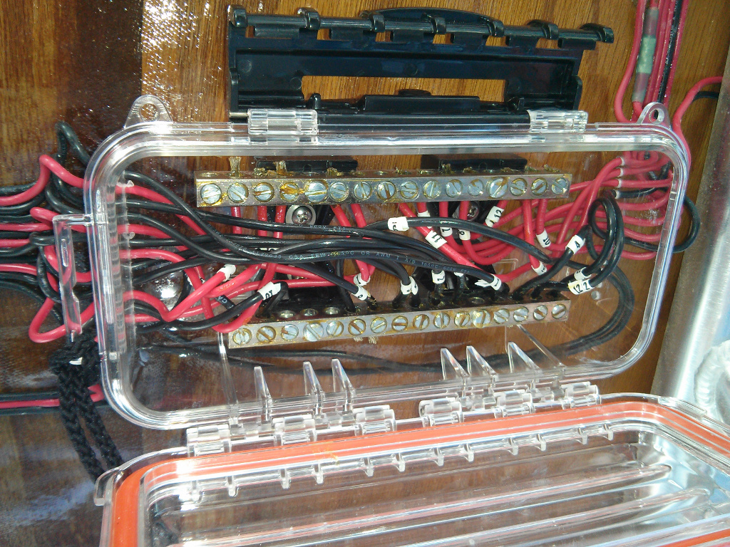
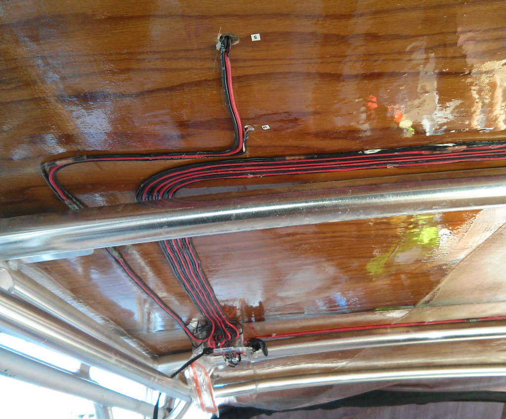
Here are the buss bars installed and hooked up. I still have to create a cover for them so that no accidents happen. They are up high and recessed behind the portside opening into the engine compartment so it is unlikely that anyone would accidentally set a tool across them but I want a cover for them anyways. The entire bus bar is coated with a di-electric grease as well as all lugs and bolts. All connections to breakers and batteries are also all greased. I am hoping this will help retard any corrosion. All cables were made by me and glue lined heat shrink wrap was applied to every joint between cable and lug. If I was unable to get heat shrink on it then I used self sealing/amalgamating silicone tape to seal the lugs/cable.
")
I installed the xantrex 5012 in the compartment under the pilot berth on starboard. It is on the other side of the bulkhead you can see behind the buss bars above and about 30 inches below it. This makes for a very short cable run from it to the buss bars to charge the batteries. I used some of the left over 4AWG cable to connect it. A bit overkill but the whole system is very much over spec to keep voltage drop to a minimum. Here is a pic of the xantrex installed. (update 9/2018 about 2 or 3 years after installing this I installed 500 watts of solar and the 60 amp mppt charge controller was installed just to the left of this charger. I used a morningstar unit that has give great service.)
")
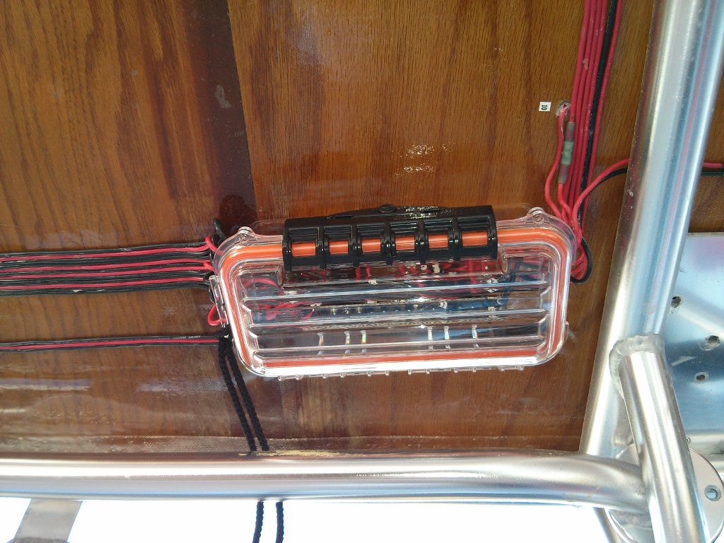
You can see the AC power line on the left and the positive and negative DC lines coming out on the right bottom. The other two lines are the remote panel data line and the grey temperature sensor that is installed on one of the batteries negative terminals. The temperature sensor allows the charger to reduce charging levels if the batteries are hot or get hot during charging to protect them from damage. The remote control panel is mounted with the other instruments at the chart table. See images below for the remote control panel.
")
")
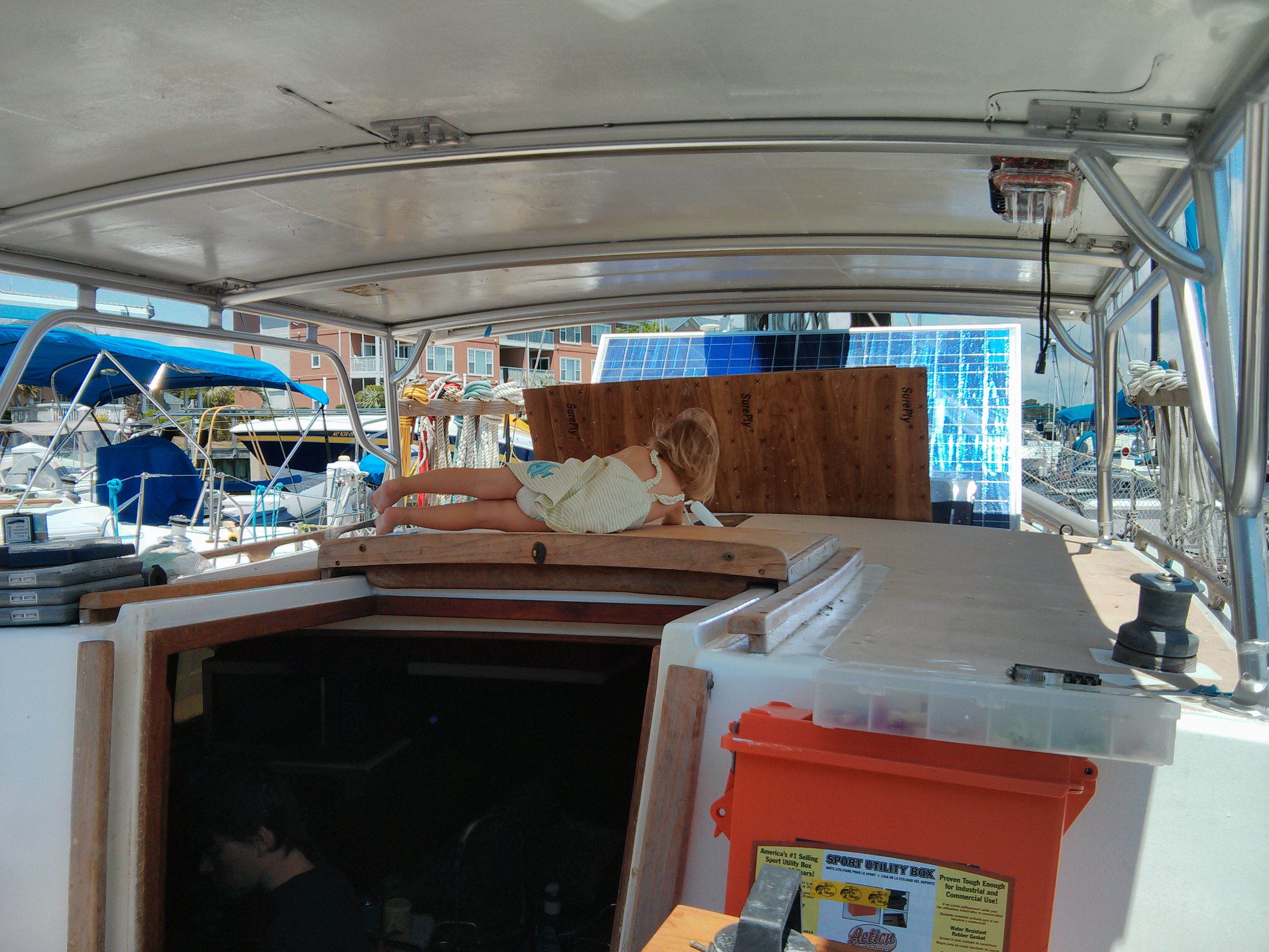
let it not be said that I did this all on my own. I was closely supervised during this whole process by
Sailor
")
Sailor up in the galley cupboard behind the stove. He has learned how to open this himself when he wants to get back in there.
Scott
September 26th 2010 onboard s/v Valkyr Southport NC.


Recent Comments